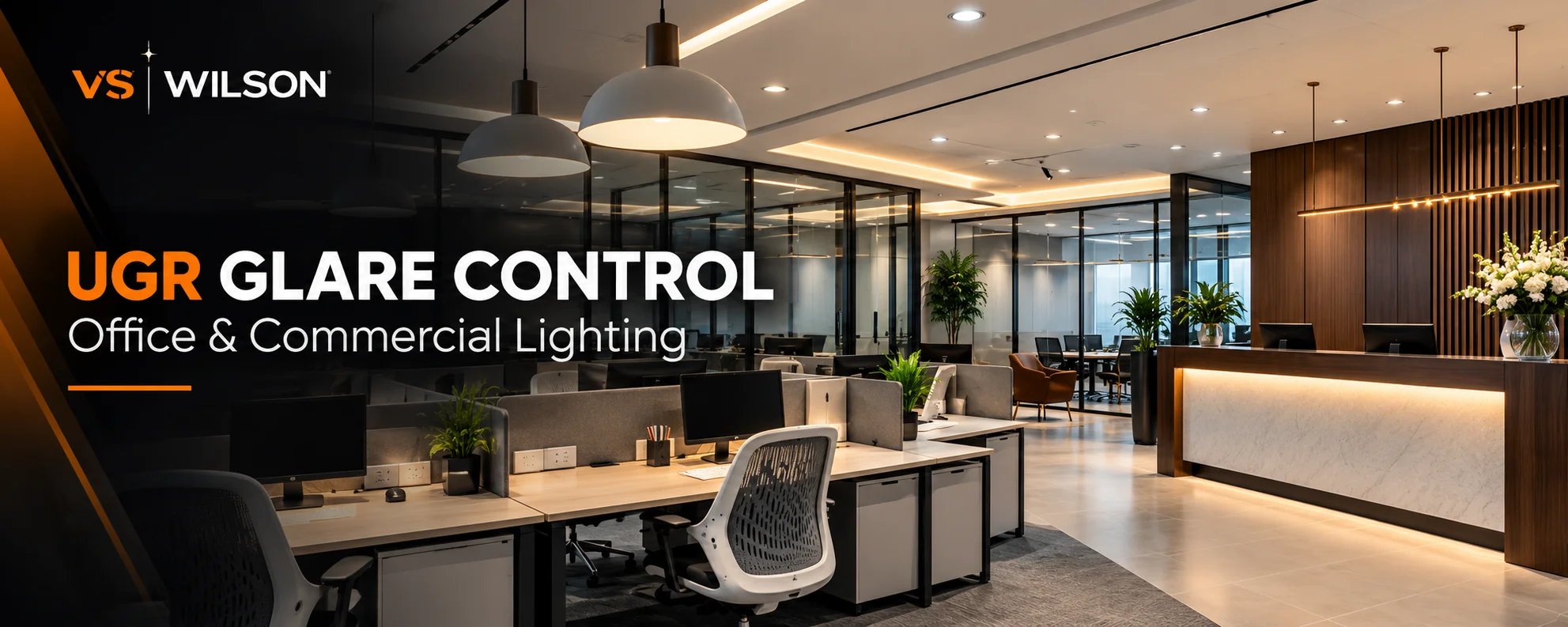
UGR and Glare Control for Office and Commercial Lighting
UGR glare control is a room-and-layout design task, not a label that belongs to a luminaire in every situation. Unified Glare Rating estimates discomfort glare from luminaires for defined observer positions using their luminance, apparent size, location, background luminance and the room arrangement. A datasheet value or UGR table is useful input, but the project result changes with spacing, mounting height, reflectances and sightlines.
For offices and commercial spaces, set the glare criterion with the project brief and applicable standard, then model the real room. Coordinate luminaire optics, layout, screens, daylight, finishes and controls. Check illuminance, uniformity and vertical light without creating bright sources in normal views. Commission the installed system at realistic dimming levels and furniture positions rather than approving glare control from fixture wattage alone.
| Design input |
Effect on glare |
Project check |
|
Luminaire distribution |
Controls high-angle intensity and source luminance |
Photometric file and product data |
|
Room geometry |
Changes apparent source position and background |
Model dimensions and mounting height |
|
Surface reflectance |
Affects adaptation and contrast |
Use realistic finish values |
|
Observer and task |
Changes sightline and screen reflections |
Define calculation positions |
|
Layout and output |
Changes source count, angle and luminance |
Calculate each scene |
Understand What UGR Represents
Unified Glare Rating is a logarithmic index used to estimate discomfort glare from electric luminaires in an indoor installation. It considers the luminance and apparent solid angle of each source, its position relative to the observer, and the background luminance. The result is tied to a viewing direction and calculation condition. It does not directly describe disability glare, reflections on screens or every individual perception.
Treat UGR as one design criterion alongside maintained illuminance, uniformity, colour quality, flicker, modelling of objects and energy. A low calculated value can coexist with poor task visibility or excessive contrast if other inputs are wrong. Conversely, a striking decorative luminaire may be acceptable in a circulation zone but inappropriate above screen-based work. The project brief should identify tasks and occupants, not just a number.
Do Not Treat UGR as a Fixture-Only Rating
Manufacturers often publish a shorthand such as “UGR below 19.” This normally reflects standard room tables, an assumed spacing-to-height ratio, specified reflectances and a particular luminous distribution. Change the room dimensions, mounting, output or observer position and the installed result can change. The table helps compare optics under its conditions; it is not a guarantee for every office.
Request the luminaire photometric file, dimensions, luminous area, flux variants and UGR table conditions. Build the selected model and output into the project calculation. If the supplier cannot state which configuration the claim describes, do not rely on the headline. VS Wilson’s office lighting design serviceframes lighting as planning, procurement and execution, which supports this project-level approach.
Set the Criterion by Space and Visual Task
Open offices, cellular offices, meeting rooms, reception areas, corridors, showrooms and collaboration zones have different tasks and viewing patterns. Common office briefs often use a UGR limit such as 19 for regular screen and desk work, but the final criterion should come from the applicable local or client standard. More demanding tasks or special occupants may require additional analysis.
Create a room schedule listing task, typical observer direction, working plane, target illuminance, glare criterion, control scene and special reflection risk. Do not extend one open-office target to lobbies or feature spaces automatically. For multinational projects, confirm which standard, national annex, client guideline and maintenance basis governs. Record all deviations and the design reason.
Model Real Room Geometry and Reflectances
UGR calculations are sensitive to room size, luminaire position and background. Use verified ceiling height, working-plane height, wall and ceiling reflectances, furniture zones and partitions. Overly bright assumed walls can lower contrast in the model, while a completed dark interior may feel much harsher. Large screens, glazing and high partitions can change actual visual conditions even when they are simplified in a standard calculation.
Coordinate the lighting model with current architectural drawings. Test credible finish ranges when selections are not frozen. Identify the longest normal view across rows of luminaires because repeated bright sources can increase discomfort. The workspace lighting design service emphasizes glare control and task visibility; accurate room information is necessary to deliver both.
Choose Optics That Limit High-Angle Brightness
Diffusers, microprismatic panels, louvres, reflectors, deep cells and indirect components manage source luminance differently. A uniformly luminous panel can appear comfortable at moderate output yet become bright when overdriven. A narrow beam may reduce direct view but create excessive contrast or hotspots. Deep-recessed optics can control high angles while reducing ceiling brightness if the rest of the design is not balanced.
Compare photometric distributions and luminous aperture, not only wattage and total lumens. Review intensity at angles likely to enter occupant sightlines. Select the exact optic and flux package used in calculations. Product substitutions require recalculation because two fittings with similar lumens may have different luminance. Mock up critical spaces when visual quality is important or unfamiliar optics are proposed.
Coordinate Layout with Desks and Viewing Directions
Placing luminaires directly in front of normal viewing directions can increase glare, while rows coordinated with desk orientation may keep bright apertures outside critical views. The solution is not simply to place every fitting between desks; spacing, uniformity, ceiling services and future flexibility also matter. Consider seated and standing viewpoints, reception counters and movement through open areas.
Import workstation plans before finalizing the reflected ceiling plan. Calculate more than one observer direction where layouts vary. For flexible offices, test representative desk orientations and provide zoning that supports change. Avoid dense symmetrical grids chosen only for ceiling appearance. A fewer-fixture design at excessive output can also be uncomfortable, so review layout and luminaire luminance together.
| Glare source |
Typical symptom |
Design response |
|
Direct luminaire glare |
Bright apertures in normal view |
Optics, position, output and shielding |
|
Screen reflection |
Veiling image or distracting patch |
Geometry, luminance control and workstation orientation |
|
Window contrast |
Eye strain near bright glazing |
Daylight control and balanced interior light |
|
Accent-light spill |
Harsh bright spots outside displays |
Beam control, aiming and accessories |
|
Over-dimming contrast |
Dark surroundings around bright tasks |
Layered scenes and vertical illumination |
Control Reflections on Screens and Glossy Surfaces
Screen discomfort depends on luminaire luminance and geometry as well as the display’s anti-reflective characteristics, tilt and orientation. A project may meet a calculated UGR value yet show bright reflected bands on monitors. Glossy desks, glass partitions, polished floors and retail displays create similar issues. Review reflected paths from likely occupant positions rather than assuming a downward beam cannot be seen.
Coordinate screen orientation away from high-luminance windows and luminaires where possible. Use suitable low-luminance optics and layouts, blinds or shades, and controllable daylight. Test dark screen content because reflections are often more visible. Do not solve reflections by reducing all light below task requirements. Combine geometry, source control and local task lighting where needed.
Balance Direct, Indirect and Vertical Light
Comfortable spaces need a reasonable relationship between task surfaces, faces, walls and ceiling. Purely direct lighting can leave vertical surfaces dark and make luminaires appear more glaring by contrast. Indirect light can brighten the ceiling and soften the environment, but inefficient placement or a very low ceiling may create hot patches. Wall washing and vertical illumination can improve adaptation when controlled carefully.
Build layers around the room function: ambient, task, vertical and accent. The interior ambient lighting service describes distributing light according to room use rather than adding fixtures randomly. For office work, model the combined scene and ensure decorative or accent sources do not become dominant in normal sightlines. Each layer needs appropriate zoning and commissioning.
Integrate Daylight and Window Glare Control
UGR addresses electric luminaires and does not fully describe discomfort from windows. Direct sun, bright sky and reflections can dominate the visual field. Assess façade orientation, glazing, nearby reflections, desk distance and seasonal sun paths. Interior lighting may need to balance adaptation without wasting energy. Blinds, shades, façade devices and workstation orientation are core glare controls.
Use daylight sensors with sensible zoning and stable dimming. Avoid switching off all luminaires beside a bright window while interior surfaces remain dark and the screen faces strong contrast. Commission sensor setpoints after furniture and finishes are installed. Provide occupants with understandable local control where appropriate, while maintaining safety and shared-space needs.
Use Controls without Creating New Visual Problems
Dimming reduces lumen output and often source luminance, but the resulting UGR and perception depend on the complete scene. Uneven zones can create bright islands. Abrupt sensor changes distract occupants, and very low dimming may reveal flicker or colour shift in unsuitable drivers. Define scenes for normal work, presentations, cleaning, after-hours and daylight response, then calculate or assess critical combinations.
Specify compatible drivers, control protocols, dimming range and transition behaviour. Group luminaires by daylight and function, not merely circuit convenience. Preserve enough surrounding and vertical light in presentation scenes for movement and facial recognition. Give facilities teams scene limits and documentation so later reprogramming does not drive luminaires above the validated output.
Coordinate Reception, Meeting and Retail Zones
Reception and meeting areas combine screens, faces, decorative fixtures and changing viewing directions. Retail and showrooms add vertical merchandise, accent beams and glossy products. A single UGR check from one desk position will miss these conditions. Define focal points and acceptable contrast while keeping bright lamps, pendants or track heads outside common sightlines.
VS Wilson describes reception lighting design and showroom lighting design as coordinated planning and execution services. For mixed commercial projects, create separate calculation views and aiming schedules by zone. Commission accent lighting with the displays in place and verify that decorative choices do not compromise screen work nearby.
Check Photometric Files and Product Substitutions
Use current, traceable photometric files for the exact luminaire, optic, diffuser, size and lumen package. Confirm test orientation, units and whether emergency or accessory configurations alter output. A calculation is only as reliable as its input. Treat copied files from a similar product or an unverified web source as a risk. Record software version and calculation settings for reproducibility.
When procurement proposes an alternate, compare distribution, luminous area, maximum intensity, output, driver, colour, dimensions and maintenance—not just efficacy and price. Recalculate representative rooms and screen-reflection risk. Update schedules and drawings after approval. A late fixture swap can change glare, spacing, ceiling coordination and control compatibility even when the new product fits the same cut-out.
Run Calculations for Critical Observer Positions
Calculate the defined standard conditions and supplement them with project-specific views. Check seated eye positions looking along and across luminaire rows, toward reception or presentation walls, and from boundary desks where windows or accent sources contribute contrast. UGR is commonly reported for a room or grid under specific assumptions; document those assumptions beside the result rather than publishing one unexplained number.
Review illuminance, uniformity, vertical and cylindrical measures where required alongside glare. Use false-colour luminance or rendered views cautiously as design aids, not substitutes for validated photometry. Identify uncertainty from future furniture or finishes and test sensitivity. The design report should show which scenes and output settings passed so commissioning can reproduce them.
Mock Up High-Risk Spaces Before Full Rollout
Mock-ups are valuable for executive offices, control rooms, trading floors, large open offices, premium retail and unfamiliar luminaires. Use the proposed ceiling height, finishes, desk, monitor and control output. View from normal positions with representative screen content. Measure illuminance and compare visual impressions across occupants. One standing view below the fitting is not a meaningful glare assessment.
Document luminaire model, output, dimming level, spacing, aiming and room surfaces. If the mock-up changes the design, update calculations and procurement. Avoid relying on smartphone photographs because automatic exposure misrepresents luminance and contrast. A structured mock-up can resolve preferences and practical issues before hundreds of fittings make changes expensive.
Commission Glare Control on the Installed Project
Commission after ceilings, finishes, furniture and major screens are in place. Verify product identity, mounting, orientation, diffuser condition, control addresses and scene output. Check representative sightlines and reflected images at seated height. Measure task illuminance and confirm daylight response. UGR is not usually verified by pointing a simple lux meter at a desk; installation checks must relate to the design model and observed conditions.
VS Wilson states that its workspace project process includes final commissioning to resolve glare or shadow issues. Define acceptance positions and scenes before site testing. Record adjustments and lock approved maximum levels where controls allow. Train facilities teams on cleaning, replacement and change control so later maintenance does not alter optics or output.
| Commissioning step |
Evidence |
Typical action |
|
Identity check |
Model, optic, output and driver match |
Replace or recalculate mismatch |
|
Scene check |
Measured output and control settings |
Balance zones and limits |
|
Sightline review |
Seated observations and screen reflections |
Re-aim, relocate or shield |
|
Daylight test |
Sensor response and blind conditions |
Tune thresholds and transitions |
|
Handover |
Calculations, schedules and final settings |
Control future changes |
Maintain Visual Comfort after Handover
Dirty or yellowed diffusers, failed LEDs, incorrect replacement drivers and unapproved higher-output fittings change luminance and uniformity. Furniture moves can put screens under bright apertures. Review glare complaints with location, time, scene, daylight and viewing direction rather than dismissing them as subjective. Individual sensitivity varies, but repeated patterns often reveal a correctable design or control issue.
Keep photometric reports, product codes, aiming schedules and control backups. Use exact approved replacements or re-evaluate alternatives. Include glare review in fit-out changes. VS Wilson’s About Us page describes a UAE-based lighting EPC approach from design through installation; ongoing performance still depends on a client maintenance and change-control process tied to the commissioned design.
Frequently Asked Questions
1. What does UGR mean in lighting?
Unified Glare Rating is a calculated index that estimates discomfort glare from indoor luminaires for defined room and observer conditions.
2. Is UGR a property of a luminaire?
Not by itself. Luminaire photometry contributes, but room geometry, reflectances, layout, output and observer position determine the project result.
3. What UGR is suitable for an office?
Many office briefs use a limit such as 19 for regular desk work, but the applicable standard and project task should set the criterion.
4. Does a UGR below 19 product guarantee compliance?
No. A product claim is normally conditional; calculate the exact luminaire and layout in the actual room.
5. Can UGR be measured with a lux meter?
A simple lux reading does not measure UGR. Verify the design model, product, output and installation, then assess representative sightlines.
6. How can office glare be reduced?
Use controlled optics, suitable output, coordinated layout, balanced surfaces, screen-aware geometry, daylight control and commissioning.
7. Does dimming always solve glare?
It can reduce source luminance, but poor layout, reflections and excessive contrast may remain; validate the complete scene.
8. Why do screens show reflections when UGR passes?
UGR does not directly capture every reflected image. Screen orientation, source luminance and geometry need separate review.
9. Do dark walls affect glare?
They can lower background luminance and increase apparent contrast, so realistic finish reflectances should be used in calculations.
10. Should workstation layouts be fixed before lighting?
They should be coordinated. If layouts are flexible, test multiple orientations and provide suitable zoning and low-luminance optics.
11. When is a lighting mock-up useful?
Use one for large, premium or visually critical spaces, unfamiliar optics, control rooms or projects with extensive screen work.
12. What should be included in glare-control handover?
Provide calculations, product codes, photometric files, final layouts, scene settings, commissioning records and replacement guidance.
Turn Glare Criteria into a Comfortable Installed Workspace
Effective glare control connects the visual task, room model, photometric data, workstation layout, daylight and commissioning into one accountable design. Share architectural drawings, reflected ceiling plan, finishes, workstation and screen positions, operating scenes and project criteria with VS Wilson through the lighting project contact page. Request a proposal covering photometric calculations, product schedules, controls, coordination, on-site aiming and post-installation verification.